USB and other J7 functions on
the M571
The M571 provides an on-board v 1.1 USB function as part of the SiS 5597/5598 chipset. M571 USB works quite well and is easy to setup and use. There is little need to use a USB card unless USB v2.0 functionality is needed.
J7 is the connector used for USB
There are two ways to connect devices to an M571. Each of these ways provide
a connection to J7. One method uses an ATX Card, which enables the entire set of functions supported by J7. The
pin-out of ATX cards used by the M571 is shared by other manufacturers, such as
Asus. The diagram below shows the J7 pin-out:
|
USB chan 2 |
+5 VDC |
2 |
|
1 |
+5 VDC |
USB chan 1 |
|
USB chan 2 |
Data - |
4 |
3 |
Data - |
USB chan 1 |
|
|
USB chan 2 |
Data + |
6 |
5 |
Data + |
USB chan 1 |
|
|
USB chan 2 |
Ground |
8 |
7 |
Ground |
USB chan 1 |
|
|
|
|
|
9 |
+5 VDC |
PS2 Mouse |
|
|
PS2 Mouse |
Clock |
12 |
11 |
Data |
PS2 Mouse |
|
|
|
Ground |
14 |
13 |
Ground |
|
|
|
Infrared Device |
IR In |
16 |
15 |
IR Hi |
Infrared Device |
|
|
Infrared Device |
IR Out |
18 |
17 |
+5 VDC |
Infrared Device |
The second means of connecting to J7 is by means of a generic Header
Cable set.
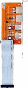
What does an ATX Card look like?
ATX cards replace one of the system card blanks in the computer case, and connect to J7 by means of a ribbon cable. This type of card will provide connectivity to both USB channels, a PS2 mouse, and an infrared device. (Note that a PS2 mouse can also be connected at the PS2 connector by the keyboard jack.) The ATX connector need not take up space used by a PCI card slot, due to the length of the ribbon cable. The picture below is one example of an ATX card:
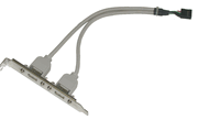
What does a Header Cable look like?
Header cables also replace one of the system card blanks in the computer case, but connect to J7 by means of 2 four or five pin connectors, one for each USB channel. This cable set is provided with 2 USB connectors in the card blank and two cables that connect to J7.
WARNING!
One very important thing to check, when you buy a generic header cable for USB, is pin 5, or the shield of the cable. If each header cable connector only has 4 pins, you need not worry about this. However, if the connectors have 5 pins, you should check to make sure that the 5th pin is not connected to the shield of the cables. Sometimes, makers of these cables will ground the shield on the case bracket blank, and also on the board pin side. Since the first 4 pins on each channel are used for the USB channel itself, some manufacturers will use the pin 5 to also connect the shield to ground.
If you connect a ground to pin 5 of J7, as you can see in the top diagram, you will apply a short directly to the +5 VDC mouse lead on J7. This will burn out the voltage trace on your motherboard! That is why any shield connections to the motherboard must be cut.
A second reason is that one should never ground a data cable shield on both ends. Often, a slight difference in potential can exist, or static electricity can then flow through the shield and induce noise into the data conductors, affecting the reliability of the connection. (This is 30 years of telecom hands on and engineering experience talking.)
It is also important for you to be sure that cut the right lead, if you have 5 conductor cables. This table should apply:
|
Pin |
Wire color |
Function |
|
1 |
Red |
+5 vDC |
|
2 |
White |
- data |
|
3 |
Green |
+ data |
|
4 |
Black |
ground/earth |
If you have one more computer, remember that you may only need one USB channel to be connected to your system, and you can use the other cable on another system.
What CMOS Settings Need to be Applied?
CMOS settings are found under “Advanced Chipset
Setup.” “ONBOARD USB” must be enabled. If you are using a USB keyboard, you
will probably want to enable “USB Function for DOS,” or you won’t be able to
use the keyboard until Windows is fully booted (assuming you are using
Windows).
What Operating Systems can be used?
The first Windows operating system with USB
capability was Windows 95, OEM Service Release 2.1 (often abbreviated “OSR 2.1”)
By right clicking on “My Computer” and checking the system’s attributes, you
must see 4.00.950B or 4.00.950C (which is Windows 95 OSR 2.5) for USB to
function. (Both of these will also allow FAT32.)
Any subsequent Windows version will also support USB.
I have used the onboard USB function on M571 systems with Windows 95 OSR 2.5, Windows 98 FE and SE, Windows 2000 Professional, and Windows 2003 Server running as operating systems. Invariably, it has worked perfectly and with no trouble. I highly recommend using onboard USB unless you need USB 2.0 capablities.
This page was last modified on 6 August 2005